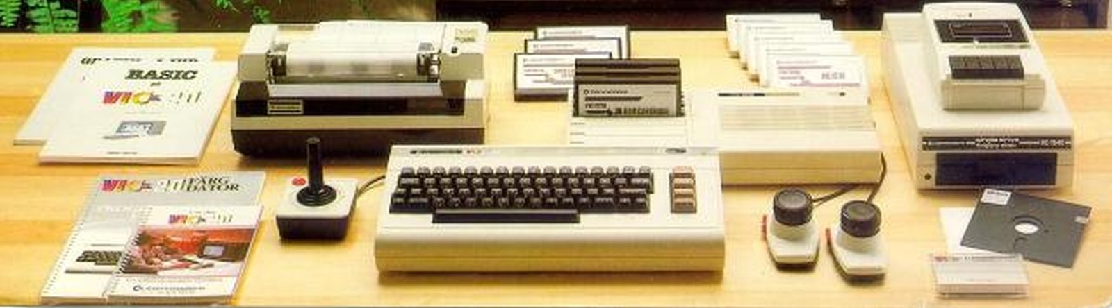

Connectors Commodore VIC 20
Power Connector
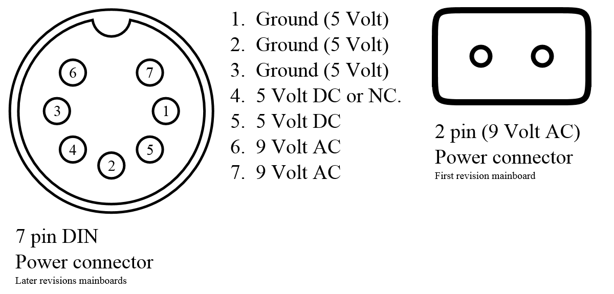
There are 2 types of power connecters, a 2 sprong 9 Volt AC and a 7 pin DIN connector.
The 2 pin connector is used on th first revision vic-20 mainboard, while the 7 pin DIN was used on the later vic-20 cr (cost reduced) mainboards.
You could use a Commodore 64 power supply on the 7 pin connector.
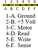
Audio / Video Connector

The +6 Volt on the video connector is used to power an external rf modulator.
Pin 4 and 5 are on most revisions connected together.
Pin 4 is often used to for the s-video mod
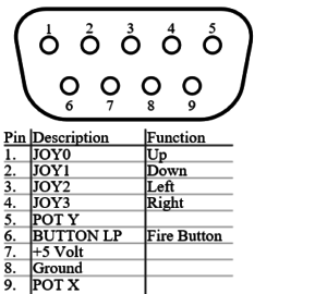
Joystick Connectors
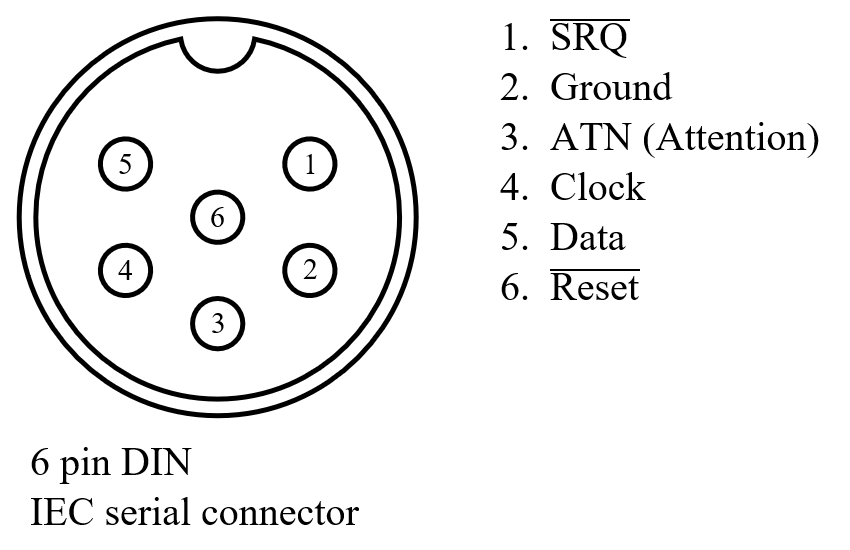
Datasette Connector
Userport Connector
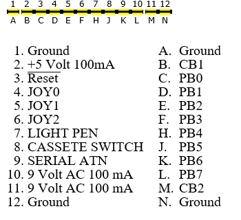
The userport PB0-PB7 is connected to the VIA 1 port B and is controllable by setting the right direction bits in the Data Direction Register Byte (DDRB) on address 37138 ($9112).
And writing or reading the port on address 37136 ($9110).
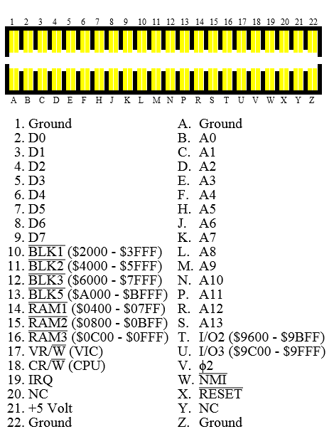
Expansion Port
Potrebbe interessarti:
 La mappa di memoria del VIC 20
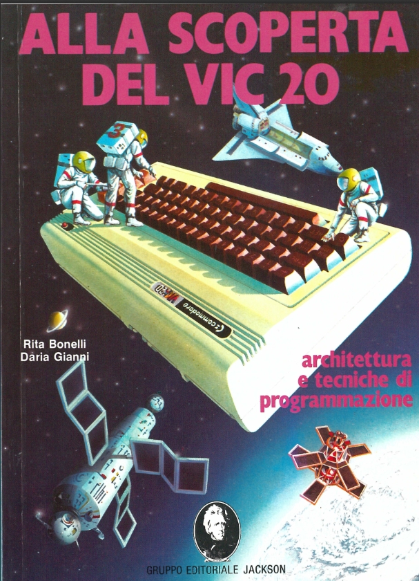 Alla scoperta del Vic 20 – Architettura e tecniche di programmazione
 Custodia protettiva per le scatole delle cartucce del VIC 20
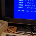
 Quando le console avevano solo una manciata di bit…
 Le periferiche del VIC vol. II
 Gestire i file per il VIC 20 con le nuove tecnologie – tutorial
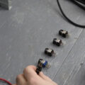 Riparare gli interruttori di accensione dei Commodore VIC 20